|
Search 650Rider.com and XS650.com using Google!
|
 | |
|
|
|
| xs650 > > Custom Work: Chop, Bob, Cafe and Flattracker - Streettracker > > Did you say Bob? No I said Bobber! > > Scratch Building a Bobber Tank |
|---|
Scratch Building a Bobber Tank
|
| Author |
Message |
kenb
Full Member

Joined: May 11, 2008
Posts: 119
Location: Flamborough, ON, Canada
|
 Posted: September 22, 2008, 7:02 pm Post subject: Scratch Building a Bobber Tank Posted: September 22, 2008, 7:02 pm Post subject: Scratch Building a Bobber Tank |
|
Hi Folks,
I've been working on a scratch build of a gas tank for my 78 XS650 Special this summer, so I decided to take a few pictures along the way and post a thread here for the benefit of those that have an interest in the process of custom building bodywork for motorcycles. I didn't see what seemed like appropiate section here for posting this topic, so I put it here in the Bobber section since that's the style of bike my XS650 will be evolving into during the course of this project. I'll post another thread later about the Bobber project itself, but for now I'll focus this thread specifically on the process of scratch building a motorcycle gas tank.
Since this is my first attempt at this type of thing, this tank is intended to be a practice run for the real one I intend to make this winter. Hopefully, I'll detect and correct most of my mistakes this time around, so that the real tank will look that much better when it is completed. I should point out that the tunnel through this tank is a little on the wide side at 4.75" accross, which is clearance I had to leave there to provide room for it to pass over the stock ignition coils that live under the tank. Since this is intended as a practice tank only, I figured the wide gap would also be handy for easy access during fit up and welding. Once I've mastered the fabrication techniques on this simplified tank, I'll design and build the real one with tighter tunnel dimensions similar to the stock XS650 tank.
Scratch building a motorcycle tank over here is a process of five steps:
1) Create the design drawings.
2) Building a buck from the profile drawings.
3) Using the buck to produce a set of flexible patterns.
4) Using the patterns to produce the actual 18 guage CRS tank sections.
5) Welding the individual sections together and preparing the surfaces for paint.
I'll tackle steps 1 and 2 in this post today.
1) DESIGN DRAWINGS
Although I used software to design the shape of this tank, I stuck with a rather simple pattern that could easily have been done with a pencil and paper. This design is simply based on circles of various diameters and center spacings to produce a teardrop inspired shape. Now that I can see the shape of the tank for real, I've noted some aspects of the shape I'm not satisfied with that I intend to change before I build the next one.
To design the tank in autocad, I divided the length of the tank into nine separate profile drawings ranging from front to back, with a 2" space between each one. I came up with the exact dimensions by drawing the shape of the tank from both the top and side views, and then extrapolating the resulting numbers to create the nine profile drawings.
2) BUILDING THE BUCK
Once I had the drawings done, I printed them off and then used them as patterns to lay their shapes out on the 1/8" thick fibre board that will form the substance of the buck. The nine patterns prior to cutting can be seen sitting on top of the board in the first picture below. Once I used a jigsaw to cut out the nine patterns cut out of the fibre board, each one was attached with epoxy to a piece of 2" thick foam insulation which will be trimmed down later to blend in the transitions betwwen each pattern.
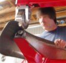
The second picture is the assembly fixture I made up from some scrap lumber and a piece of ABS pipe. This assembly fixture will ensure that the patterns and the foam inserts will be attached together straight and true and along the proper slope. This fixture also provided a handy platform to hold it securely to the bench when the outer surfaces were blended in and a thin coat of bondo was applied.
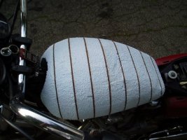
To assemble the parts, I first cut away the foam on the inside of the tunnel area on each section and then lowered it into position on the ABS pipe. The second piece was added and joined to the first one with expoxy (anything else melts the foam!), and then each additional section was added in order until I had assembled the whole buck. Once the parts were connected, I used a small trimming saw to carve away the excess foam and to sculpt the proper curvature into the front and rear of the tank shape. After the tank shape was carved out of the foam to my satisfaction, I applied a thick coat of white latex primer inside and out to protect the foam from being dissolved by the bondo that will be added next.
To finish up the buck, I applied and sanded a thin coat of bondo to provide a smooth even surface for taking the flexible pattern from. This resulting pattern will be my road map for shaping up the 4 individual parts out of 18 guage CRS. Once the bondo was cured and sanded, I followed it up with a coat of red-oxide primer.
I'll spread the associated pictures out over a couple of post after this one.
NEXT UPDATE: Step 3: Making a flexible tape pattern.
Ken
| Description: |
| Some of the sections joined together with expoxy. |
|
| Filesize: |
63.31 KB |
| Viewed: |
163 Time(s) |

|
| Description: |
| The assembly fixture used to ensure proper alignment and slope. |
|
| Filesize: |
69.48 KB |
| Viewed: |
108 Time(s) |

|
| Description: |
| The 9 profile drawings ready to trace out on 1/8" thick fibre board. |
|
| Filesize: |
41.34 KB |
| Viewed: |
102 Time(s) |

|
_________________
Has anyone seen that key I left in the chuck?
*************************************
Check out Ken's Metalshaping Gallery at:
home.cogeco.ca/~kenb2/index.html |
|
| Back to top |
|
 |
Jake68
650Rider Supporter


Joined: Mar 23, 2007
Posts: 841
|
| Posted: September 22, 2008, 7:04 pm Post subject: Re: Scratch Building a Bobber Tank |
|
Looking forward to more pics man 
|
|
| Back to top |
|
|
kenb
Full Member
Joined: May 11, 2008
Posts: 119
Location: Flamborough, ON, Canada
|
| Posted: September 22, 2008, 7:07 pm Post subject: Re: Scratch Building a Bobber Tank (MORE PICTURES) |
|
Some more pics:
| Description: |
| First buck sections after shaving the foam down a bit. |
|
| Filesize: |
75.28 KB |
| Viewed: |
112 Time(s) |

|
| Description: |
| Side view of buck during assembly. |
|
| Filesize: |
71.23 KB |
| Viewed: |
110 Time(s) |

|
| Description: |
|
| Filesize: |
82.31 KB |
| Viewed: |
115 Time(s) |

|
_________________
Has anyone seen that key I left in the chuck?
*************************************
Check out Ken's Metalshaping Gallery at:
home.cogeco.ca/~kenb2/index.html |
|
| Back to top |
|
|
kenb
Full Member
Joined: May 11, 2008
Posts: 119
Location: Flamborough, ON, Canada
|
| Posted: September 22, 2008, 7:14 pm Post subject: Re: Scratch Building a Bobber Tank (MORE PICTURES) |
|
And some more: (the system seems to cut me off at 3 pics for some reason. Image size maybe?)
| Description: |
|
| Filesize: |
68.15 KB |
| Viewed: |
115 Time(s) |
|
| Description: |
| Here's the buck after a coat of white latex primer to protect the foam from the bondo. |
|
| Filesize: |
50.38 KB |
| Viewed: |
111 Time(s) |

|
_________________
Has anyone seen that key I left in the chuck?
*************************************
Check out Ken's Metalshaping Gallery at:
home.cogeco.ca/~kenb2/index.html |
|
| Back to top |
|
|
Jake68
650Rider Supporter
Joined: Mar 23, 2007
Posts: 841
|
| Posted: September 22, 2008, 7:28 pm Post subject: Re: Scratch Building a Bobber Tank |
|
| COOL!...
|
|
| Back to top |
|
|
kenb
Full Member
Joined: May 11, 2008
Posts: 119
Location: Flamborough, ON, Canada
|
| Posted: September 22, 2008, 7:28 pm Post subject: Re: Scratch Building a Bobber Tank |
|
Here's the finished buck ready for taking a pattern from:
| Description: |
| Finished buck, ready to provide a flexible pattern. |
|
| Filesize: |
36.4 KB |
| Viewed: |
114 Time(s) |

|
| Description: |
| Finished buck coming off the assembly jig for the last time. |
|
| Filesize: |
44.39 KB |
| Viewed: |
115 Time(s) |

|
| Description: |
|
| Filesize: |
85.72 KB |
| Viewed: |
108 Time(s) |

|
_________________
Has anyone seen that key I left in the chuck?
*************************************
Check out Ken's Metalshaping Gallery at:
home.cogeco.ca/~kenb2/index.html |
|
| Back to top |
|
|
Finksies
Full Member

Joined: Jan 26, 2008
Posts: 178
Location: Windham, NH
|
| Posted: September 28, 2008, 2:55 pm Post subject: Re: Scratch Building a Bobber Tank |
|
| Lookin sweet so far. You must be ultra patient. What are u using for a welder?
|
|
| Back to top |
|
|
kenb
Full Member
Joined: May 11, 2008
Posts: 119
Location: Flamborough, ON, Canada
|
| Posted: September 30, 2008, 12:27 pm Post subject: Re: Scratch Building a Bobber Tank |
|
| Finksies wrote: |
| Lookin sweet so far. You must be ultra patient. What are u using for a welder? |
Thanks Finksies,
aybe not so patient, as much as just having too much fun! I generally have a tendency to be a real fickle for detail, and sometimes I have to catch myself lest I take it too far.
I'll be gas welding the tank with a Henrob 2000, as it's a more suitable weld from the metalshaping point of view. The finished welds are softer than anything I can do with a MIG, which reduces the tendency for the welds to mark up the anvils and upper wheel on my English Wheel. Gas welding with the Henrob also produces a smaller HAZ (heat affected zone) than I can get with a TIG, so the warping and distortion is kept to a minimum. Although it's not the ideal solution for all welding tasks, it sure fits the bill when welding up thin sheetmetal.
Ken
_________________
Has anyone seen that key I left in the chuck?
*************************************
Check out Ken's Metalshaping Gallery at:
home.cogeco.ca/~kenb2/index.html |
|
| Back to top |
|
|
|
|
You cannot post new topics in this forum
You cannot reply to topics in this forum
You cannot edit your posts in this forum
You cannot delete your posts in this forum
You cannot vote in polls in this forum
You cannot attach files in this forum
You can download files in this forum
|
|
|
|
| |
Check out the new Honda CB750 Forum at CB750.com! A site dedicated to the great Honda SOHC and DOHC CB750.
Check out the new Yamaha XS400 Forum at XS400.com!
Yamaha xs650
xs650, xs, 650, forum, links, chopper, custom, yamaha, parts, forum, info,
information, bb, bulletin board, XS650 650Rider, Free Unrestricted xs650
forum, Personal photo albums, Post images in Forum, News columns, Daily blog,
Links, Event calendar, Information for Yamaha XS650
Interactive software released under GNU GPL,
Code Credits,
Privacy Policy
|
|