|
Search 650Rider.com and XS650.com using Google!
|
 | |
|
|
|
| xs650 > > Motorcycle Systems > > Electrical > > Rotor rewinding |
|---|
| Author |
Message |
kd4eqt
Full Member


Joined: Sep 14, 2005
Posts: 10
Location: Julian, North Carolina
|
 Posted: August 3, 2006, 11:22 am Post subject: Rotor rewinding Posted: August 3, 2006, 11:22 am Post subject: Rotor rewinding |
|
While restoring my ’83 Heritage Special I found that, among other things, the resistance of my rotor was lower that it should have been. Since this is just a coil of wire wound around a form the only thing that could cause this is a short between two or more of the windings effectively reducing the length of wire that generates the magnetic field. Being that the cost of a new rotor is ~$180, if my memory serves me correctly, and me being the type person that refuses to pay for something that I can do myself and learn something in the process, I choose to tackle the rewinding of my rotor. After all it’s only a coil of wire.
I will attempt to describe the steps that worked for me. Since I did this almost a year ago I am going by memory, so you would do well to read this and then develop your own ideas about how it should be done. Any given measurements should be verified for your specific application, since my memory may not be accurate.
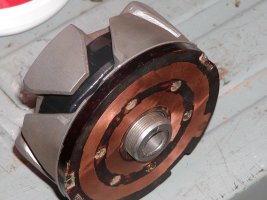
Start by removing the contact plate. Be very careful when working with this plate. If it’s damaged you’ll be buying a new rotor since I know of no source for just the plate. Disconnect the two wires of the coil that are connected to the contact plate using a soldering iron. Then remove the contact plate, which is held down by 6 socket head cap screws. These are in the area between the two copper bands and are covered by plugs. The plugs are epoxy and can be removed by digging out with a knife. This plate should be cleaned very carefully with steel wool to remove any oxidation. Also clean the two tabs where the wires were connected removing any solder or epoxy. Set this aside for later.
Once the contact plate is removed the two halves can be pressed apart. The two sides are splined onto the center shaft. Only one half is needed to be removed. This is best done with a hydraulic shop press. You’ll have to figure out the best way to block it and press the side off. Be careful not to bend the tabs, these have to stay in line otherwise it will rub the inside of the stator. Since the coil is sealed in epoxy it will not come apart in one nice unit. The wire will string out as the coil is separated. Pay attention to the direction that the wire is wound. It shouldn’t make much difference, but doesn’t hurt.
I was lucky enough to get mine apart without damaging the wire and then stretched it out in the yard to see how much wire was needed. It measured 325 feet. The wire size was measured to be 22AWG. Check with a local started or alternator shop to see if they will sell you about a pound of 22AWG magnet wire. This wire is coated and is made for winding magnets and coils. I was able to by a pound which was more than enough for $15.00. It can also be order online.
When the rotor housing is apart and the wire has been removed it will have to be cleaned to remove the old epoxy compound otherwise you will not be able to put the new coil in. The best thing I found to do this was a bead blaster. It removed the old epoxy and left the housing looking brand new.
The next step is to build a form to wind the new coil on. I used a piece of PVC pipe and two PVC blank end caps. I think the pipe diameter was 1.5” but can’t remember for sure. The outside dimension of the pipe was slightly larger than the hub diameter of the rotor so the finished coil will slide easily onto the rotor hub. It can’t be too big or you won’t be able to get all the wire in and balance will be a problem since the coil could be off center. Cut the PVC pipe to a length that is slightly less that the width between the two halves when pressed together. Use PVC glue to fix the end caps onto the pipe to make a form for winding the wire. I drilled a hole in each end and used a bolt to make a shaft that I held in a lathe. You will have to fashion a way to hold the form steady and spin it at low RPMs. A drill mounted in a vise would possibly work.
When I wound my coil I calculated the outside diameter for the wire size, width and inside diameter of the coil so I would know when enough wire had been wound. If I did it again I would maybe measure the wire first to know exactly how much I had on the coil. Either way, start by taping several inches to the outside of the form. This will be one of the connection points. Start winding the wire around the PVC hub keeping the turns even, tight and next to each other. The neater job that is done the more wire that can be put on the coil and you need at least 325feet to get the correct resistance. As the first layer is done just start back the other way letting the wire lay in the groove created on the first layer. Continue this process until the required length of wire is on the form. Take your time and go slow. Once all of the wire is wound leave several inches at 90 degrees from the piece that is hanging out from the start. These will be the connection points and need to line up close to the tabs on the contact plate. Tape the ending wire to the side of the form. Measure the diameter of the coil and verify that it will fit back in the housing. If not you may have to unwind and rewind tighter or neater.
I used epoxy to coat the coil before the form was removed. Use a thin coat so that the coil will not be too big to fit back in the housing. Once it is dry carefully break off one side of the form and coat the edge of the coil with epoxy. Once dry the coil can be removed from the form. Coat the other side and the wrap with one layer of electrical tape to hold the coil together. Measure the resistance of the coil. It should be close to 5.25 ohms.
The finished coil can be placed into the rotor housing and pressed together. Make sure that the wires align with the tabs on the contact plate before pressing together. Also make sure that the coil does not get nicked of scratched. If so you will have to start over since these nicks will short out and create the same problems. Press the housing back together using a shop press making sure to align the splines and also that the tabs are evenly centered with each other.
Coat the inside of the housing and coil with epoxy to seal the oil and prevent movement in the form. Make sure the epoxy is even around the rotor and doesn’t interfere with the contact plate or the outside of the rotor. Neatness counts. If the epoxy is even there should not be a need to balance the rotor.
Once everything is dry, re-install the contact plate in the reverse order. The coating on the wire will have to be removed on each end before soldering to the tabs. Emory cloth can be used to sand off the coating. Only remove enough of the coating to be able to make a good solder connection. Leave a short length of wire at each contact tab but not so much that it gets slung out and cut by the stator. Even better once connected put some epoxy over he wire and contact to seal it and prevent movement. The screw holes can be left uncovered. Be careful to not over tighten the screws and crack the plate.
These are the steps that I used when I rewound my rotor almost a year ago and it has worked perfectly since then. It will require some patience and some know how but it can be done. I am not responsible if you damage a good core that could be exchanged for a rebuilt rotor. You will have to make the decision if this is something that you can do.
I hope this information helps someone repair a faulty rotor or at least understand better the workings of their 650. If I get the chance maybe I’ll put together a document on how I rebuilt my electronic voltage regulator and rectifier unit. This is a much more in-depth task, but also possible.
Happy riding,
Tony
| Description: |
|
| Filesize: |
440.07 KB |
| Viewed: |
649 Time(s) |
|
| Description: |
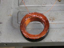
| Completed coil epoxied, ready to install. |
|
| Filesize: |
456.65 KB |
| Viewed: |
684 Time(s) |
|
| Description: |
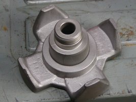
| Rotor half pressed apart and bead blasted |
|
| Filesize: |
477.11 KB |
| Viewed: |
634 Time(s) |
|
Last edited by kd4eqt on May 1, 2007, 4:02 pm; edited 3 times in total |
|
| Back to top |
|
 |
xsjohn
Full Member

Joined: Jul 30, 2006
Posts: 5857
Location: North Carolina USSA
|
| Posted: August 3, 2006, 1:04 pm Post subject: Re: Rotor rewinding |
|
Very Very good. I hoped someone would tackle this.
I also have an idea that 3/16 rare earth magnets
could be drilled and glued into the pre cdi rotors.
I have bought the magnets because I have 2 of the older rotors
and only the rebuilt original cdi rotor for my 1980. I have
wound many guitar pickups and lowpass speaker coils.
Thanks Ole Yamaha Mechanic John Underwood
|
|
| Back to top |
|
|
kd4eqt
Full Member
Joined: Sep 14, 2005
Posts: 10
Location: Julian, North Carolina
|
| Posted: August 3, 2006, 1:29 pm Post subject: Re: Rotor rewinding |
|
I don't see why this would not be possible. I haven't looked at a pre-CDI rotor but I would assume they are the same except for the permanent magnet.
Good luck,
Tony
|
|
| Back to top |
|
|
kd4eqt
Full Member
Joined: Sep 14, 2005
Posts: 10
Location: Julian, North Carolina
|
| Posted: August 8, 2006, 9:03 am Post subject: Re: Rotor rewinding |
|
The wire size is 22AWG and not 30. Thanks to xsjohn for questioning that.
Tony
|
|
| Back to top |
|
|
Charliekilr
Full Member

Joined: Jul 29, 2006
Posts: 23
Location: GA.
|
| Posted: August 8, 2006, 4:52 pm Post subject: Re: Rotor rewinding |
|
If I send you my rotor will you do mine 
|
|
| Back to top |
|
|
xsbrian
New Member


Joined: Apr 28, 2009
Posts: 9
Location: st paul mn
|
| Posted: May 13, 2009, 1:55 pm Post subject: Re: Rotor rewinding |
|
| This is such an ideal solution. I can't believe I was actually thinking about paying someone $150+dollars to essentially "do this for me." This is probably the number one BEST thread on this site considering these rotors have been junk yard gold nuggets for YEARS. I'm almost inclined to wrap two or three just to shelf or sell later on down the road.
|
|
| Back to top |
|
|
|
|
You cannot post new topics in this forum
You cannot reply to topics in this forum
You cannot edit your posts in this forum
You cannot delete your posts in this forum
You cannot vote in polls in this forum
You cannot attach files in this forum
You can download files in this forum
|
|
|
|
| |
Check out the new Honda CB750 Forum at CB750.com! A site dedicated to the great Honda SOHC and DOHC CB750.
Check out the new Yamaha XS400 Forum at XS400.com!
Yamaha xs650
xs650, xs, 650, forum, links, chopper, custom, yamaha, parts, forum, info,
information, bb, bulletin board, XS650 650Rider, Free Unrestricted xs650
forum, Personal photo albums, Post images in Forum, News columns, Daily blog,
Links, Event calendar, Information for Yamaha XS650
Interactive software released under GNU GPL,
Code Credits,
Privacy Policy
|
|